audio filter circuit Audio Circuits Circuit Diagram The low pass filter circuit which is the prime part of this project, filters a frequency spectrum or any mix of frequencies. The frequencies above the cut-off frequency of the circuit are bypassed to the ground by the capacitor C. This is a capacitive low pass filter which has a resistor connected in series and a capacitor in parallel with the output.

Next, high pass filter is designed to attenuate frequencies from 0 to 9.75 kHz. Cut-off frequency is set to 9.75 kHz and standard capacitor value for audio circuit design chosen to be 0.01 micro Farads. To calculate Resistor values for High pass filter Equation 2 is used. Where: m = magnitude coefficient f c = 9.75 kHz Cs = 0.01 micro Farads D

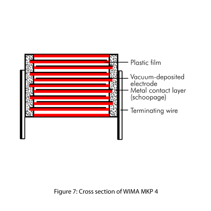
Selecting Capacitors to Minimize Distortion in Audio Applications Circuit Diagram
This helps ensure that the audio signal is of the highest possible quality. The most common type of noise filter circuit is a passive low-pass filter. This uses inductors and capacitors to block higher frequency signals and allow lower frequencies to pass. Other types of filter circuits include high-pass filters, notch filters and bandpass

For example, hi-fi audio goes down to 20 Hz. For some headroom, it's a good idea to design your circuits with high pass filter rolloffs at 10 Hz or so. The impedance magnitude of a capacitor is 1 / 2πfC, with f in Hz, C in Farads, and the result in Ohms.

Audio Signal Generators and Filters Circuit Diagram
learn more about filter design. 1.1 Filters and Signals: What Does a Filter Do? In circuit theory, a filter is an electrical network that alters the amplitude and/or phase characteristics of a signal with re-spect to frequency. Ideally, a filter will not add new frequen-cies to the input signal, nor will it change the component frequencies of